|
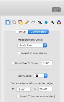
The document properties tab has two parts: Setup and Coordinates.
Setup
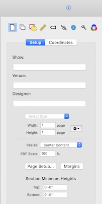
Document Properties/Setup lets you edit basic information about the plot. This information appears in the header of a report when it is printed and in generated title blocks.
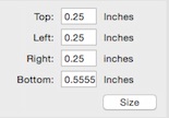
This tab is also used to set the size of the drawing area. Standard sizes are available in the Select Size popup. The drawing size can also be set in terms of the pages it will take to print. The page size shown is for the document zoomed to "Actual Size". The current zoom changes the size of the printed output. Factors that affect the size include the margin settings as well as paper size and scale selected with the Page Setup button.
When a document is exported as a PDF it can be scaled at 200%, 50%, or to the current zoom. A standard document size selected from the popup menu will be increased or reduced if the PDF Scale value is not 100%. This is done so that the document, when output at this percentage, will be the desired size. For example, you can increase the standard 1/4" scale to 1/2" by exporting a PDF scaled at 200%. For the PDF output to match a standard size, the drawing area needs to be 50% smaller than it would be if the output was at normal size.
A change in document size can shift the contents in several ways based on different reference points. The default is to move the graphic center of the objects in the drawing to the center of the new size. The first option in the popup is to change inward to or outward from the corner with the lowest x and y values, normally the lower left. The second option is arrange the existing objects so that the origin of the user coordinates is centered in the document. The third option is to use the center of the current document boundary and expand or contract the new size evenly on all sides of that point The difference in between Center Current and the default Center Content is that the former refers to the center of the drawing regardless of what it contains and the latter to the center of the objects contained in the drawing.
The popup menu in the size tab contains some useful functions for setting the size of the document. First, you can set the size to be exactly equal to the bounds of the objects contained in the drawing (Match Contents). Conversely, you can set the size to be in multiples of whole pages. This option can be useful when you don't necessarily want to change the size from that shown but do want to apply one of the options such as centering the content. The Scale to Single Page When Printing option will fit the entire document on a single page instead of printing across multiple pages. You have a chance to review the printing options when you choose to print.
The size of the section is automatically set by the size of the document and the location of its objects. At the bottom of the Document Properties tab, you can specify upper and lower heights for the section that are above or below those determined by the objects in the plot.
|