|
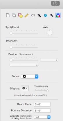
The beams tab controls options related to beams and their display.
The Spot/Flood slider control helps set the spot/flood of selected lights that have a variable beam.
The Axis control helps set the axis rotation of selected lights that have an oval beam such as PARs.
The Intensity slider control sets an intensity level of selected lights and creates/updates their beams.
The Device slider sets the level of a selected light's channel that has been selected by the address popup to the right of the slider. In order to respond to this slider, the selected light must have a channel assigned and be of a kind that has device addresses in the key. If the selected device address has a table of defined values, these may be selected from the popup below the device slider.
The Focus popup contains commands that allow copy and paste of focus locations between lights. These commands are also found in the Format menu.
Beams can be displayed using either the beam angle or field angle from a symbol's key entry. (Note: not all fixtures in the standard libraries have values for both beam and field).
Beams are normally displayed as filled ovals using the color of the light that produced them. When they are created they are placed at the back of the layer of the light that produced them. Because this may block the view of other layers, the transparency of the beam display can be varied. See view menu help for a description of the other beam display options.
The Beam Plane is the height of the plane on which beams are displayed.
Beams are projected as ovals onto the plane. When a beam cannot be projected onto the plane because its path is close to parallel, the beam is displayed as a cone. When the height of a light is too close to the beam plane or the light is pointed away from the beam plane, the beam may not be displayed at all.
A light's "bounce" focus point can be included in reports. The bounce point is a calculated point that is located on a plane relative to the light's position. The bounce point will be calculated at the Bounce Distance below the position. Bounce points take into account either the light's Z offset or the key's default Z offset depending on the option in the Format preferences.
The Illumination Points display shows intensity levels calculated for different angles that you select from the popup menu in this tab. .
|